How-To: Sending data to the Data Portal
⚠ Important Note :
This guide applies to the ifm mobileIoT IoTBuilder CR31xx.package version 3.0.0.0 or newer.
The guide below is using a CR3171 firmware version 3.1.0.
Use cases
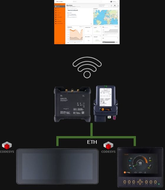
Sending data from ecomatDisplay
ℹ Good to know:
The communication between the ecomatDisplay and a CR3171 is encrypted via HTTPS.
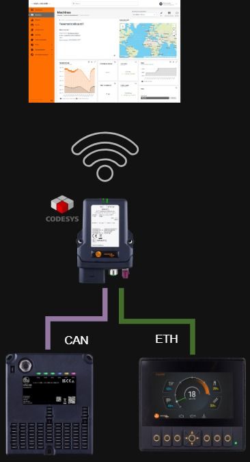
Sending data from the CR3171
ifmRawCAN.library
Prerequisites
Log into the WebUI of the CR3171 by following CR3171 WebUI Login Set a password for the file upload to the device by following Setting password for file upload. Set a password for the API by following setting password for api.
⚠ Important Note :
Close all instances of the service pack in which you are going to install the packages

⚠ Important Note :
The versions may differ after your installation, due to newer released packages.
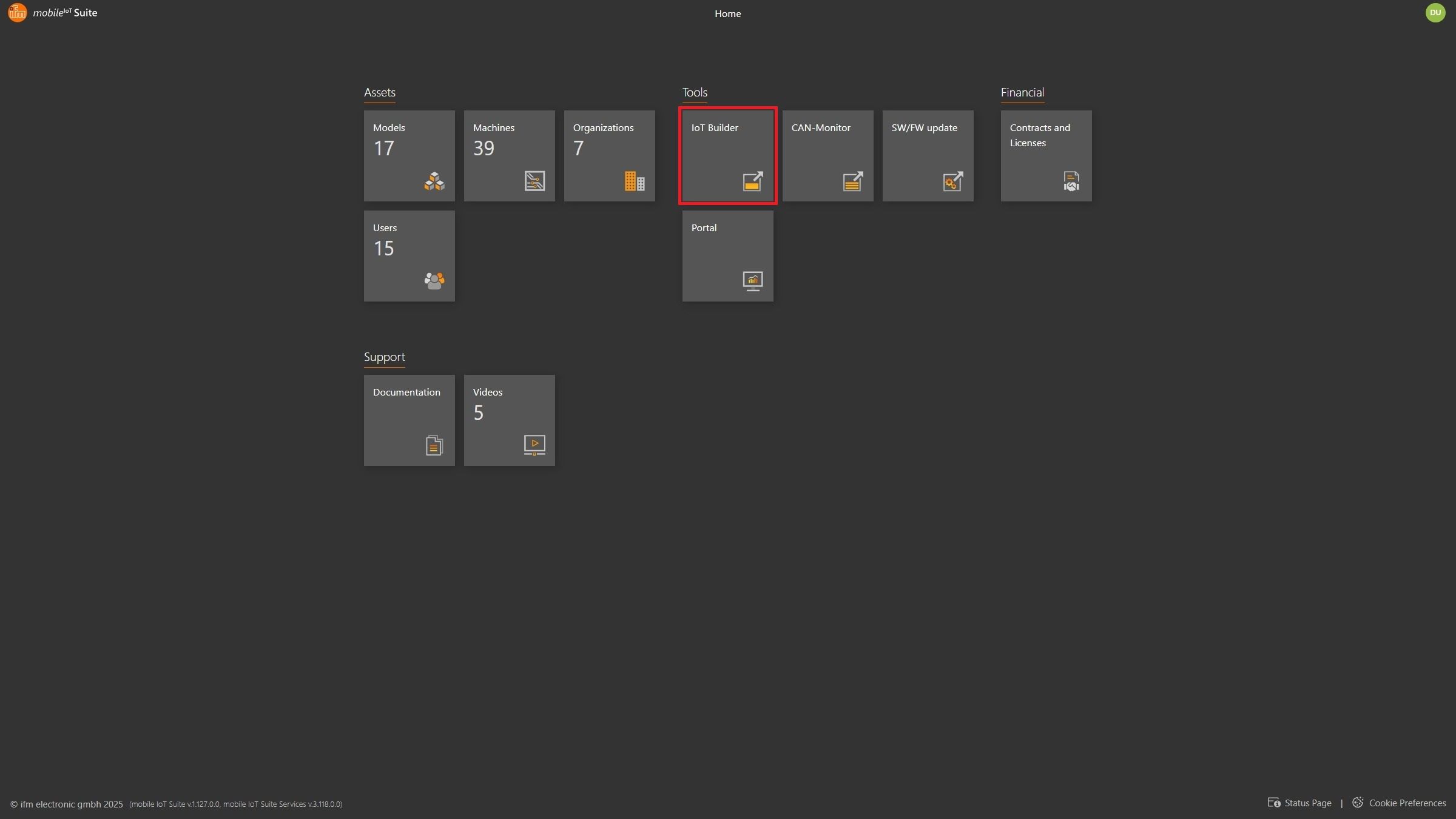
Step 1: IoT Builder in mobileIoT suite
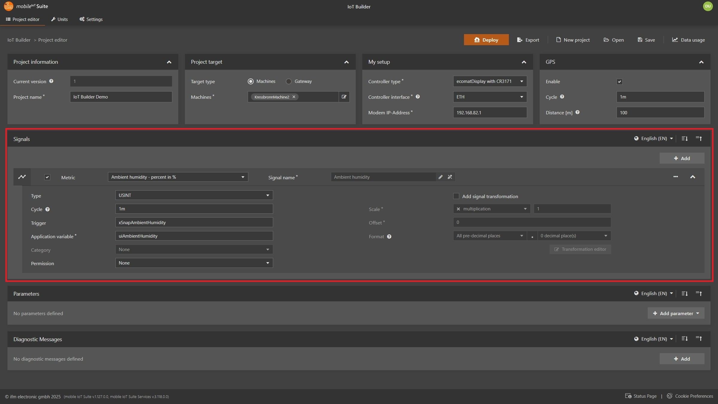
Project settings and signal definition
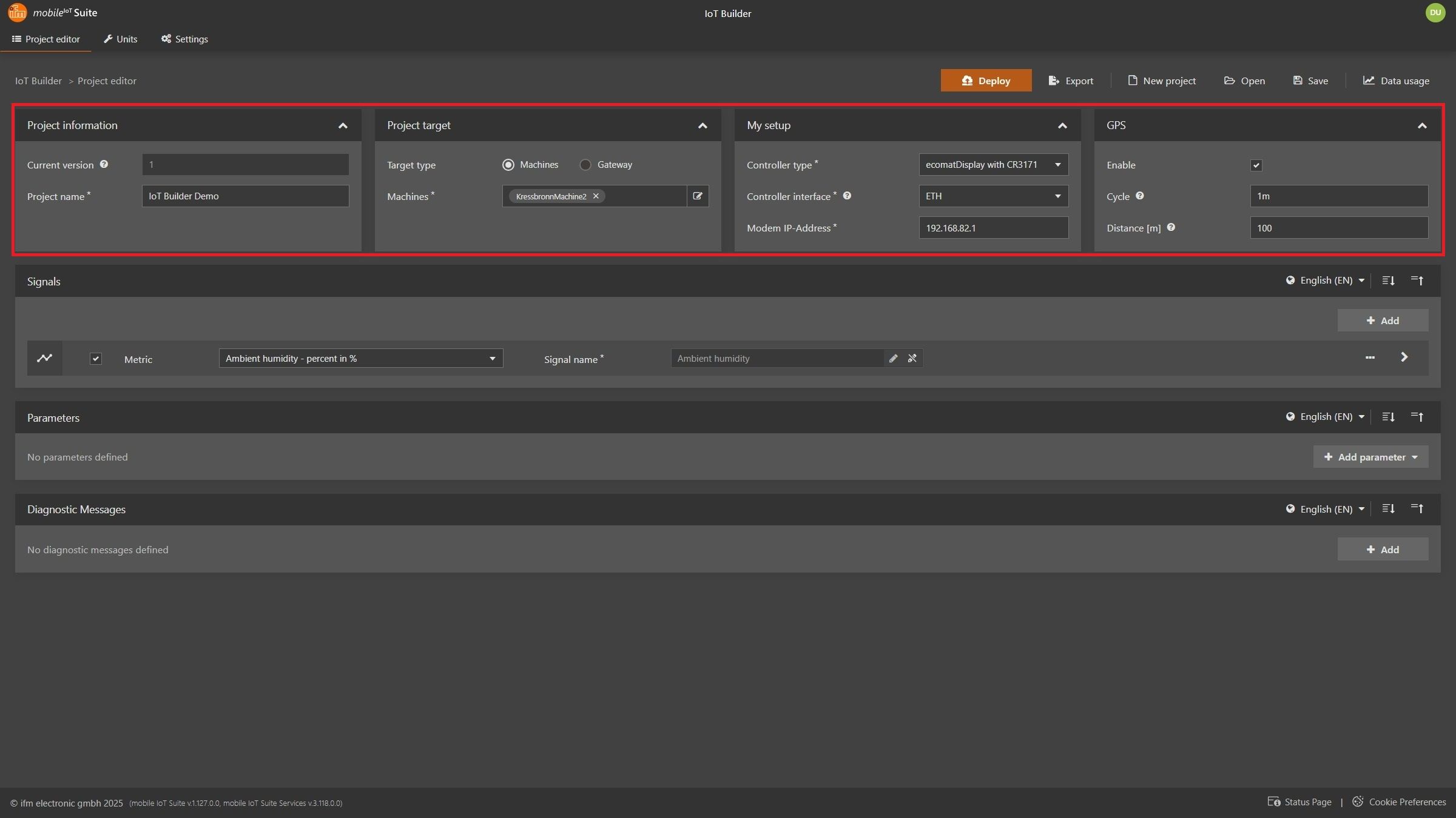
Project information: Name of your project Project target : Selecting a machine: Data Portal configuration of selected machine is getting adjustedSelecting a gateway: Only export of IoT Builder project settings and CODESYS related filesMy setup: Controller type: Device the IoT Builder is going to run onecomatDisplay with CR3170: Any ecomatDisplay together with a CR3170 ecomatDisplay with CR3171: Any ecomatDisplay together with a CR3171 CR3171: On the CR3171 itself Controller interface: Always ETHModem IP Address: IP of the mobileIoT gatewayGPS Enable: Enable if GPS data is needed (enabled by default on CR3171 FW ≥ 1.7.0) Cycle: Time interval for GPS data collection Distance: Not used for CR3170 and CR3171
Signal type: Standardized metric or create own metric Signal details: Customize name and unit Configuration Cycle : Time interval for data collection
⚠ Important Note :
Cycle time must be minimum 15 seconds.Trigger : Variable in CODESYS triggering logging of the Application Variable. Define this variable if you want to log the value of the variable on an event. Application variable : Name of the CODESYS variable holding the value Type : CODESYS data type Category : Up counter: The value is counting up Down counter: The value is counting down Permission : Access control in Data Portal
Transformation : Optional value transformation
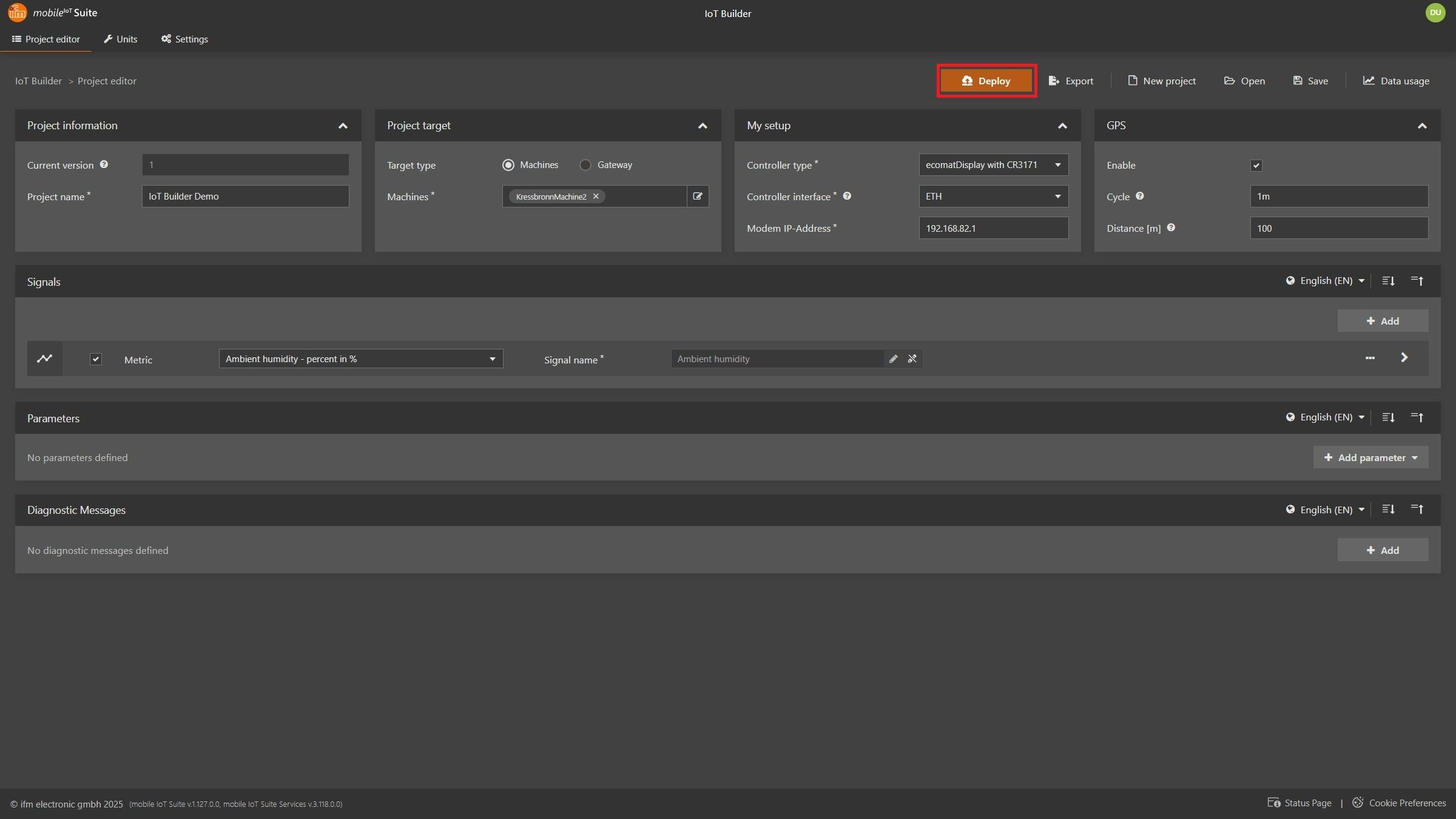
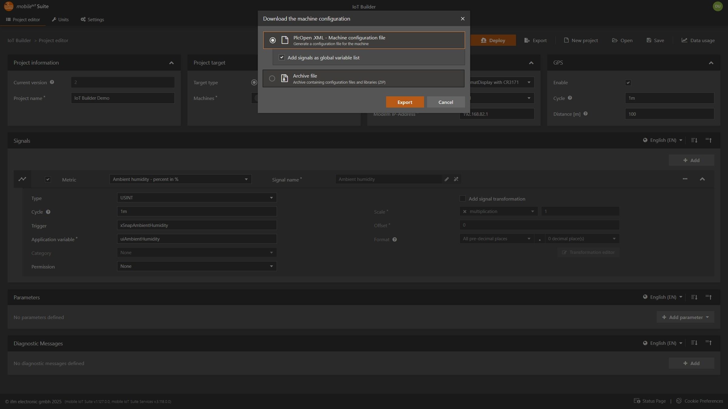
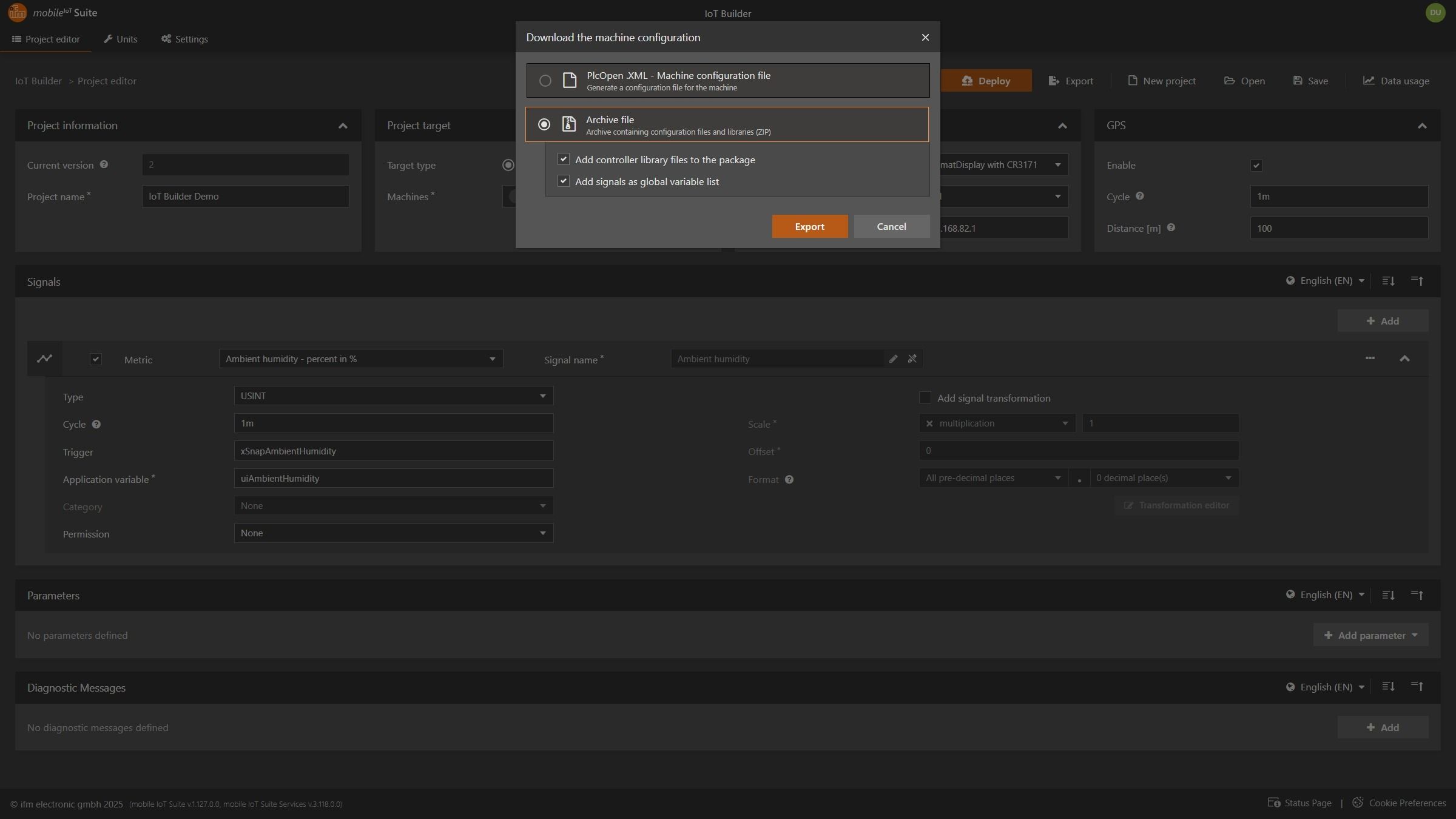
Deployment to your machine
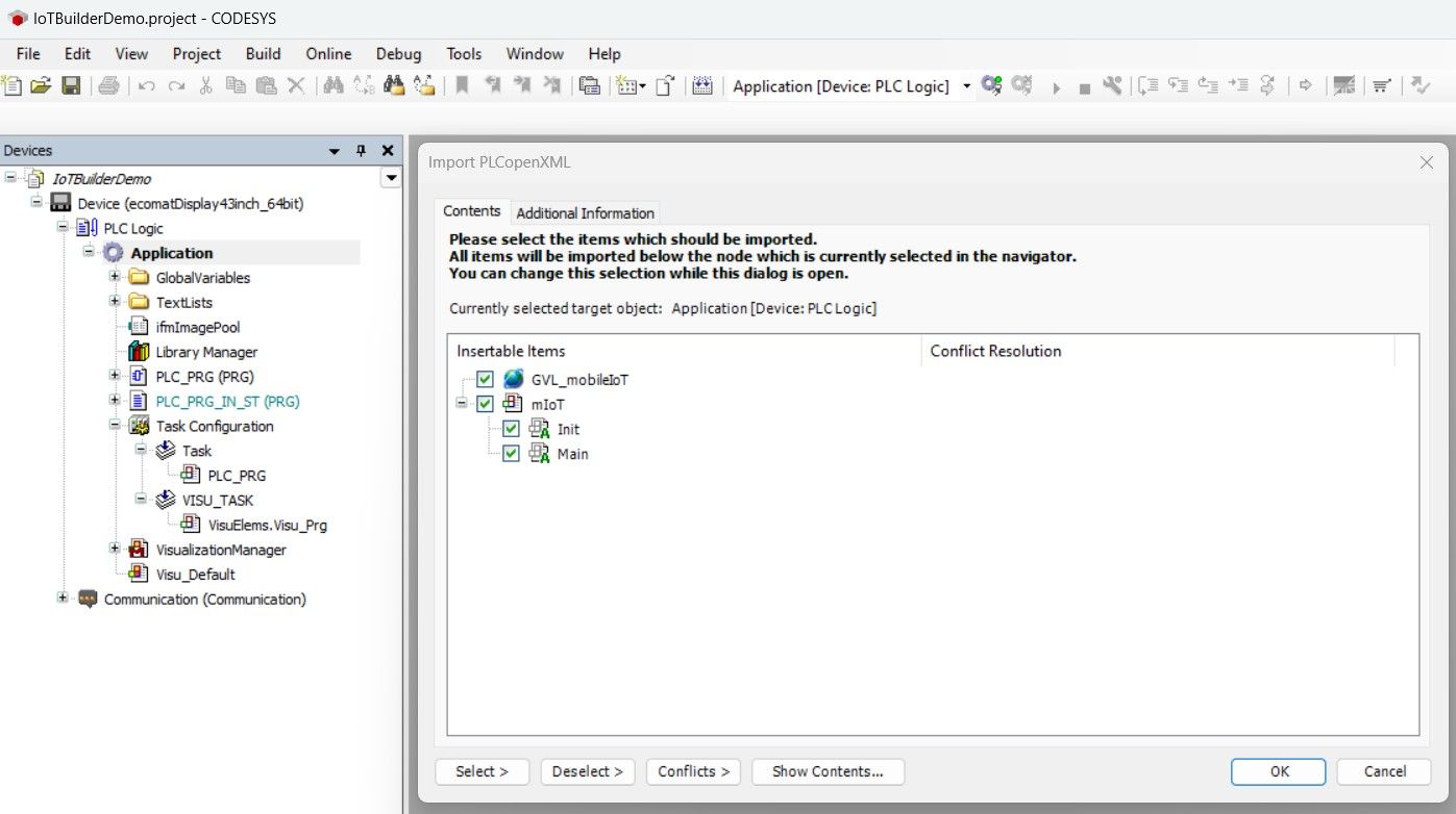
Step 2: Import into CODESYS
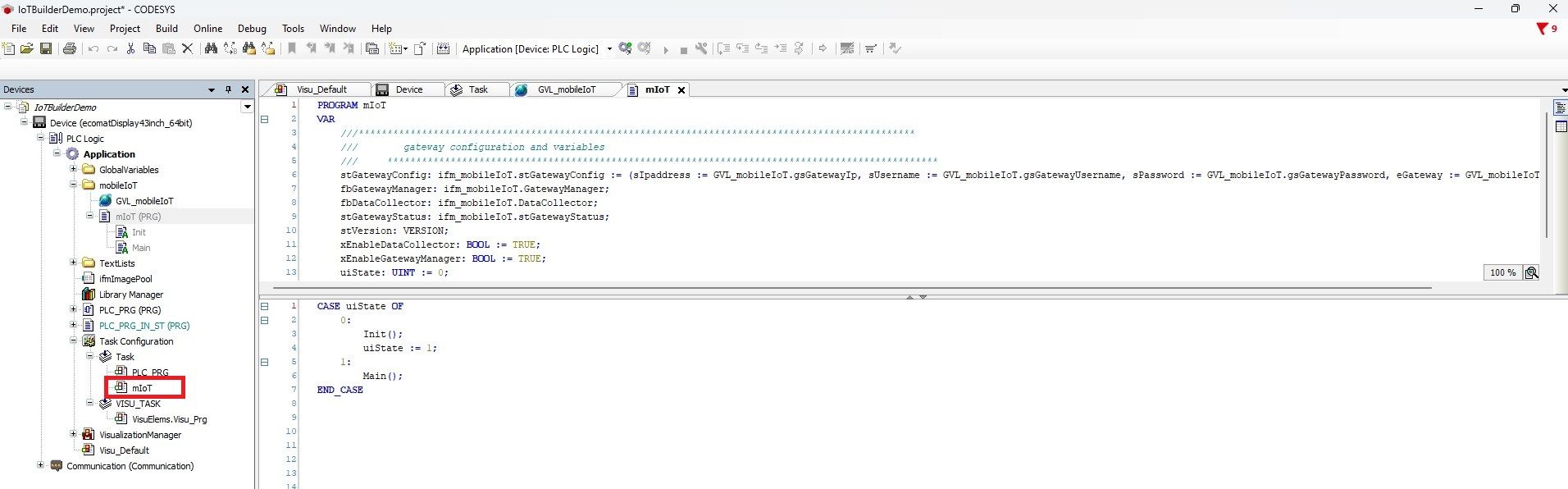
Importing mobileIoT program
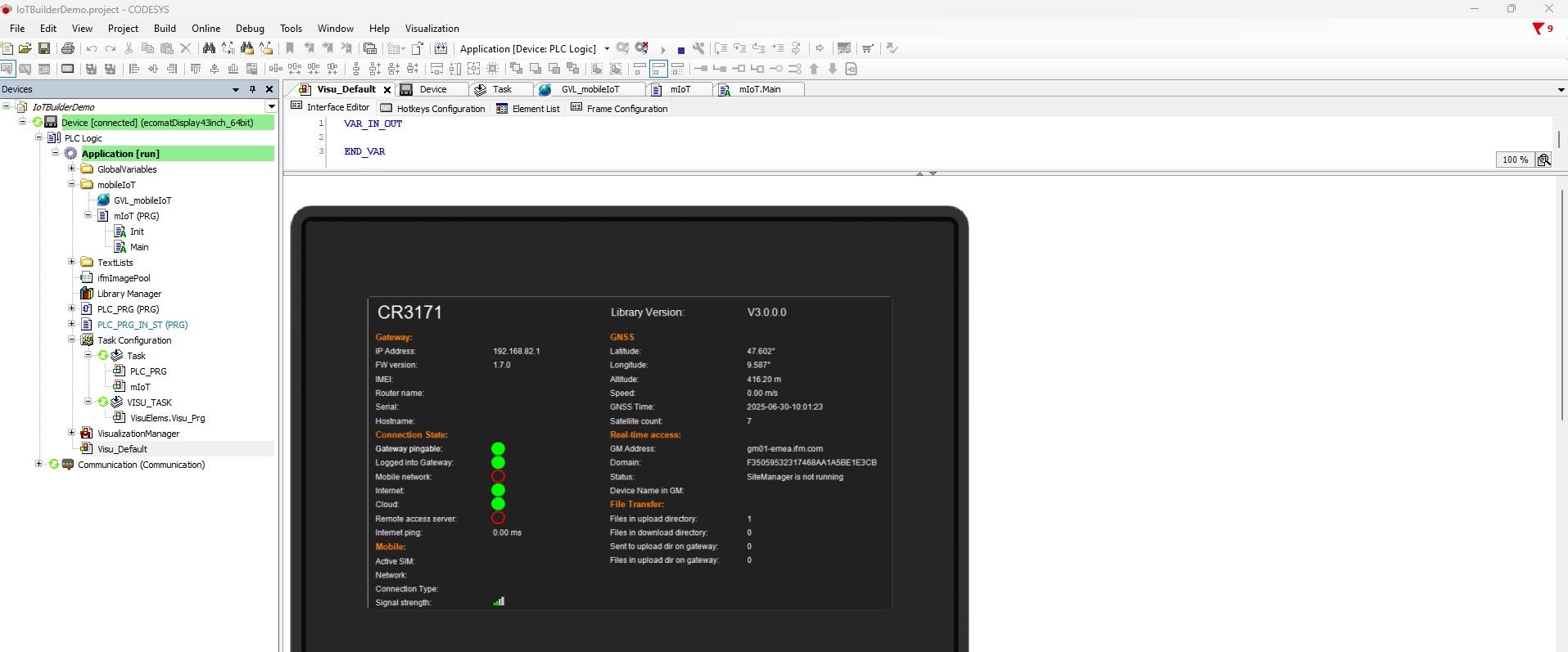
Afterwards you should see the following:
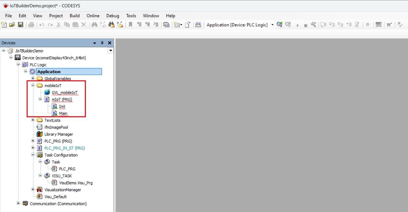
⚠ Important Note :
The folder mobileIoT must appear inside the Applications tree.
If not, make sure you have selectedApplication when importing the project.xml file.
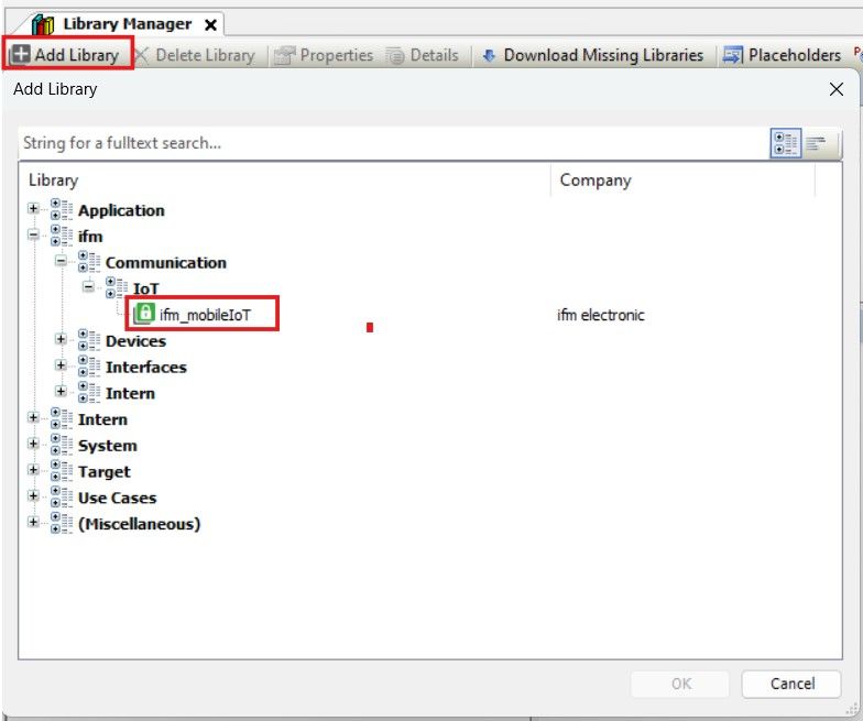
Library Manager -> Add Library -> Select or search for ifm_mobileIoT
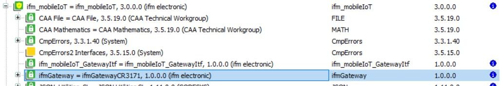
Library Manager -> Placeholders -> Check for empty libraries and select a version
⚠ Important Note :
For system libraries beginning with version 3.5 you should never choose a library above your service pack and patch version.
For example: When using SP19 Patch 7, you should not use a system library above V3.5.19.7
⚠ Important Note :
Repeat this process until all placeholders are set.
⚠ Important Note :
Due to a bug in the CAA File Library, you need to manually set the library version of the CAA File Library to a maximum of 3.5.17.0 when using retain variables.
Make sure, that the mIoT task is assigned to a task by drag and dropping the PRG on any task
Setting user and password
Open GVL_mobileIoT Set the username for gsGatewayUsername :
The username for the CR3171 isapi. Set the password for gsGatewayPassword :
This is the password which you have set in the WebUI for API.Set the password for gsFileUploadPassword :
This is the password which you have set in the WebUI for File upload.
⚠ Important Note:
All passwords need to be base64 encoded.
To do this use for exampleBase64 Converter
⚠ Important Note:
Usernames for CR3170:
admin (FW >= RUT9_R_00.07.06.3)
root (FW < RUT9_R_00.07.06.3)
Adding values to your signals
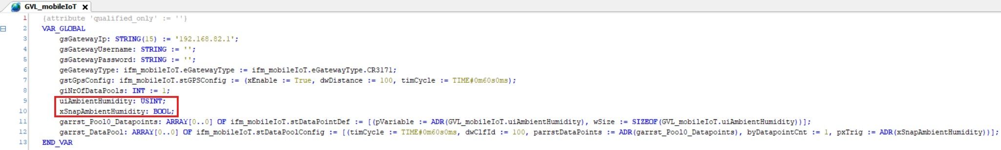
GVL_mobileIoT.uiAmbientHumidity := 40;
Snapping a value of your signal
uiAmbientHumidity xSnapAmbientHumidity
xSnapAmbientHumidity := TRUE;
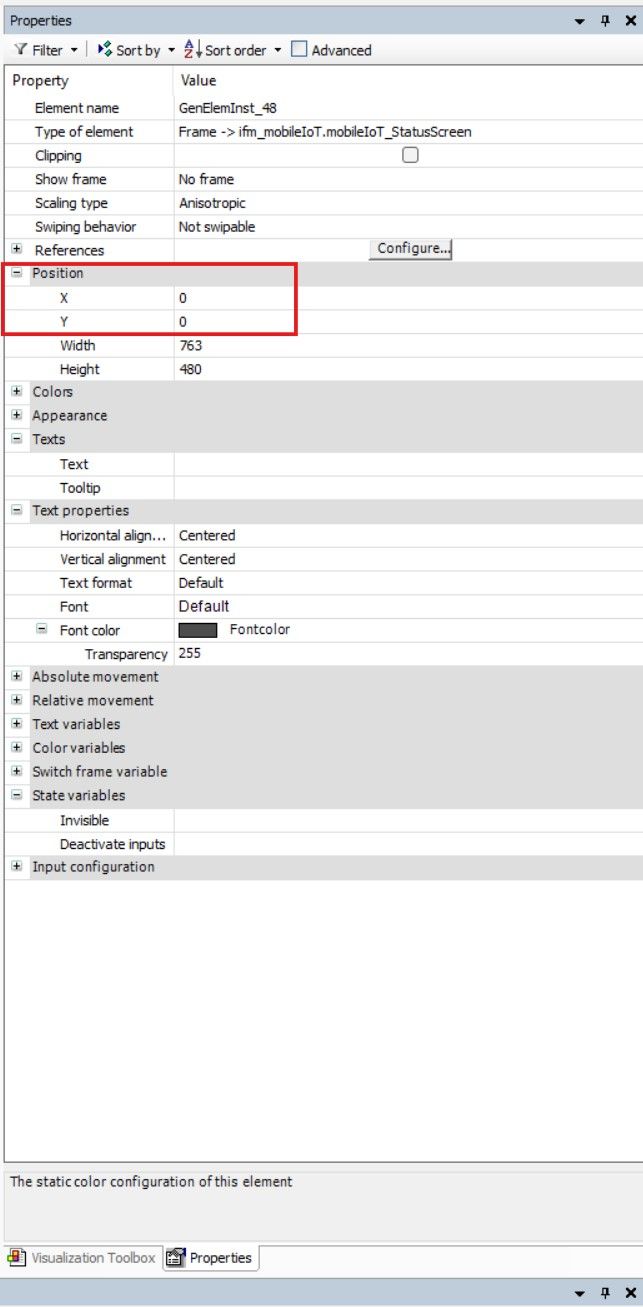
Adding mobileIoT status screen
Open or create a visualization Navigate to Visualization Toolbox -> ifm_mobileIoT -> Drag and Drop the mobileIoT_StatusScreen into the visualization
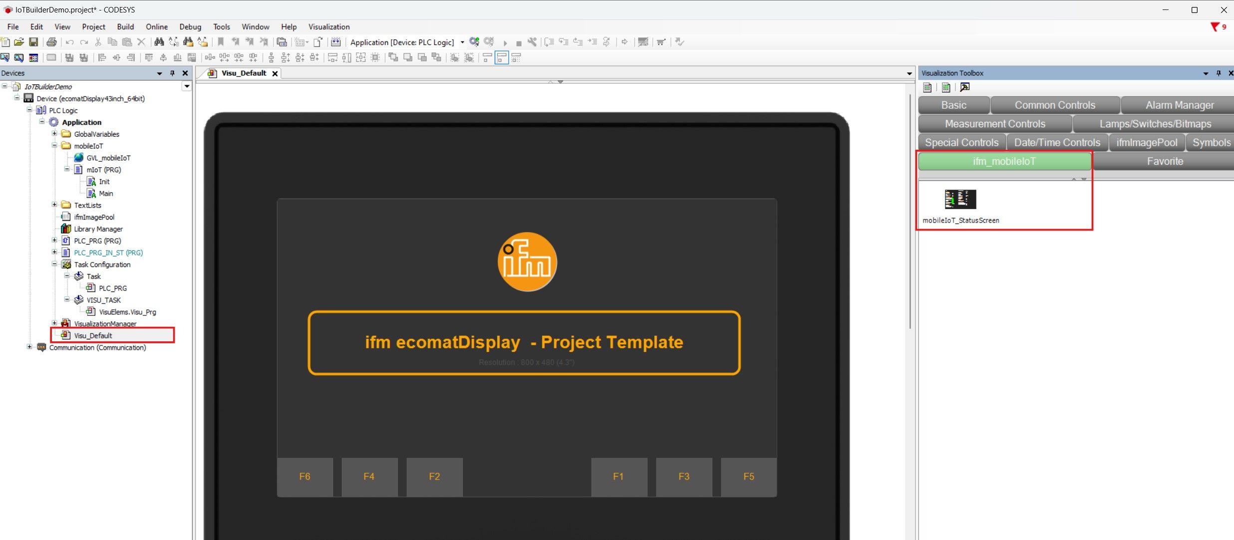
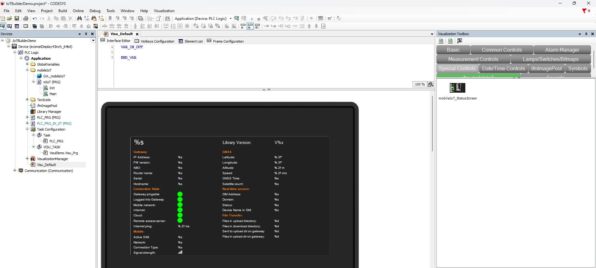
⚠ Important Note :
Due to missing information from device side, its possible that not all values are getting displayed.
Library compatibility
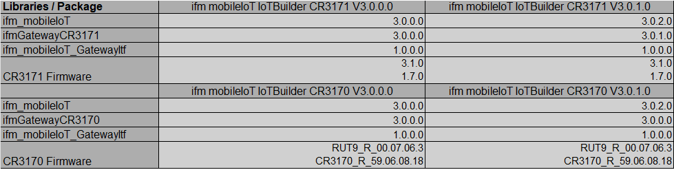
Library Release History
ifm_mobileIoT library
V3.0.0.0
initial release
V3.0.1.0
Changes
If the library is not officially released by ifm, the mobileIoT_StatusScreen will add an "RC" (release candidate) to the screen.
Bug fixes
The uiNrOfFilesInDownloadDir and uiNrOfFilesInUploadDir outputs of the GatewayManager function block were lower than the actual values.
ifmGatewayCR3171 library
V3.0.0.0
initial release
V3.0.1.0
Changes
Cloud-to-Machine: While files are being transferred from the cloud to a machine, the file extension is .part until the transfer is complete. If the transfer from the cloud to the machine stops for any reason, the .part file remains and is removed when the same file name is transferred again. Cloud-to-Machine: If a file with the same name already exists on the target device, the newly transferred file will be given the extension _1, followed by _2, and so on.
Bug fixes
Machine-to-Cloud: The transfer to the cloud stopped after an unpredictable amount of time