Virtual Wi-Fi bridging profiles

⚠ IMPORTANT:
This section is only valid if the Virtual Ethernet WiFi Bridge is
ENABLED

This profile allows to setting up the bridging of Ethernet and WiFi. This makes the two interfaces act as one, allowing wired and wireless access to the same network.

Next in the list of Network Profiles is the Virtual Ethernet-WiFi bridging profiles in this section we will be looking in how to configure this option.

Profile name

Name of the bridged connection, this is a read only value which can not be changed.

Active

This option allows to enable or disable the bridging of Ethernet and WiFi. This makes the two interfaces act as one, allowing wired and wireless access to the same network. When bridging is enabled, all other individual Ethernet and WiFi profiles become locked and disabled, because the corresponding interfaces now below to the bridge. Also, should the Ethernet or WiFi device be disabled when bridging becomes enabled, then these interfaces will be reenabled automatically. This needs to happen, because bridging requires both interfaces to be present and active.

Routing metric

Routing metric, lower values have higher priority. Set to -1 for automatic assignment based on interface type. This option will allow you to prioritize one interface over the other when accessing the internet, depending on interface or connection availability.

  • default = -1

Operating mode & Security
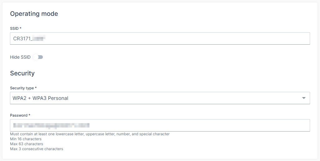
This section defines how the CR3171 gateway connects to a wireless network when Virtual Ethernet-Wi-Fi Bridging is enabled. It includes configuration options for SSID visibility, security protocols, and authentication credentials.

SSID

The SSID (Service Set Identifier) is the name of the Wi-Fi network the gateway will broadcast or connect to.

  • Default : CR3171_<LAST 4 DIGITS OF MAC>
Hide SSID

Controls whether the SSID is visible to nearby devices.

  • Default : OFF (SSID is visible)
Security type

To comply with EU Radio Equipment Directive (EU-RED), the available Wi-Fi security types have been restricted to modern, secure standards. Only the following options are supported:

  • WPA2 + WPA3 Personal
    This hybrid mode allows compatibility with both WPA2 and WPA3-capable clients. It uses Pre-Shared Key (PSK) authentication and ensures a secure baseline while supporting legacy devices.
  • WPA3 Personal only (SAE)
    This mode enforces WPA3 using Simultaneous Authentication of Equals (SAE), offering enhanced protection against dictionary attacks and forward secrecy. It is recommended for environments where all clients support WPA3.
⚠️ Legacy and enterprise security types such as WPA/EAP, OWE, and unencrypted modes are no longer supported. This change ensures compliance with EU-RED requirements and strengthens overall network security.
Password

Depending on the selected security type:

  • For WPA2 + WPA3 Personal, the password is the Pre-Shared Key (PSK) used for authentication.
  • For WPA3 Personal only (SAE), the password is processed using SAE, which provides mutual authentication and resistance to offline attacks

Band and IP configuration method
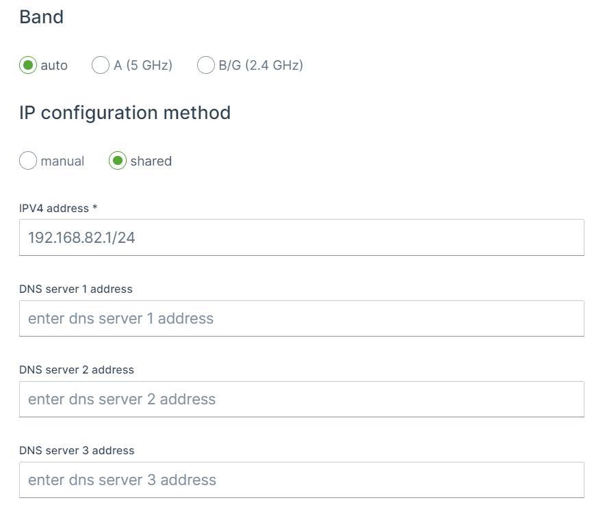
Band

This option configures the 802.11 frequency band of the network, i.e. the device will not join the network if the band does not match, even if all other options are compatible.

Options:
  • auto
  • A (5 GHz)
  • B/G (2.4 GHz)
Channel

When either band option A or B/G are selected one need to set the Wireless channel.

Wireless channel to use for this connection, the value of zero means, that the channel will be chosen automatically. Explicitly setting this option will ensure that the device only joins a network on the specified channel.

IP configuration method

This section defines how the CR3171 gateway assigns IP addresses to connected devices when Virtual Ethernet-Wi-Fi Bridging is enabled. The selected method affects how clients obtain their IP configuration and how the gateway manages network traffic

Shared (Gateway as DHCP Server)
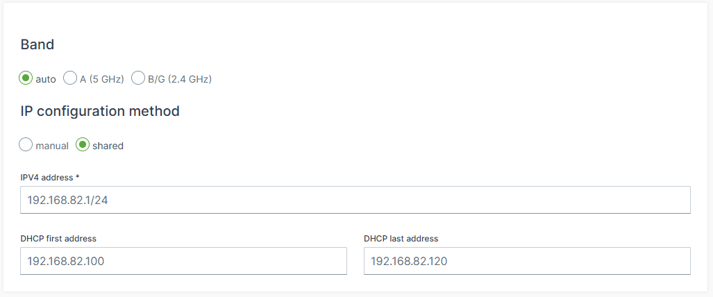
In Shared mode, the CR3171 acts as a DHCP server for connected clients. This mode is suitable when the gateway is expected to manage IP address distribution independently, without relying on an external DHCP server.

Configuration Options:

  • IPv4 Address:
    Default : 192.168.82.1/24
    The static IP address assigned to the CR3171 on the bridged network.
  • DHCP first address (new)
    Default : Will be assigned automatically
    The starting IP address of the DHCP pool. Clients will be assigned addresses beginning from this value.
  • DHCP last address (new)
    Default: Will be assigned automatically
    The final IP address of the DHCP pool. This defines the upper limit of assignable addresses.
🛡️ These new DHCP range settings allow administrators to control the scope of IP distribution, which is particularly useful in segmented networks or when reserving parts of the subnet for static devices.
Example:

If the gateway IP is 192.168.82.1/24 , you might configure:

  • DHCP first address: 192.168.82.100
  • DHCP last address: 192.168.82.150

This setup allows the gateway to assign IPs from .100 to .150 while keeping .1–.99 and .151–.254 available for other purposes.

Manual (Static IP Configuration)

In manual mode, the IPV4 Address defines the network and mask, the device IP is set through IPV4 Gateway, which is described below.

IPV4 Address

IP address used for either static IP, when method is set to manual or DHCP server configurations when the shared method is selected. The CIRD notation is used to define the subnet mask.

By using e.g. 192.168.82.1/24 the device will be part of the 192.168.82.0 network and will allow access or communication from IPs in the range of 192.168.82.1 - 192.168.82.255

🎯 Tip: As security measure it is advisable to tighten the allowed IPs on the network as possible, for instance to use /29 or 255.255.255.248 subnet to only allow 6 address on the network, as 192.168.82.0 is the network address and 192.168.82.7 is the broardcast address and 192.168.82.1 - 192.168.82.6 remains available.
Example - default setting

192.168.82.1/24 will result in:

  • Network = 192.168.82.0/24
  • Host = 192.168.82.1
  • Static IP range = 192.168.82.2 - 192.168.82.10
  • Dynamic IP range = 192.168.82.11 - 192.168.82.254
  • Broadcast IP = 192.168.82.255
Example 2 - Ready for controller and display & secure

When a network is setup with ifm controllers and displays which are by default respectively configured with 192.168.82.247 and 192.168.82.245 , it make sense to

192.168.82.240/29 will result in:

  • Network = 192.168.82.240/29
  • Host = 192.168.82.241
  • Static IP range = None as only 6 addresses are available (6/10) = 0
  • Dynamic IP range = 192.168.82.242 - 192.168.82.246
  • Broadcast IP = 192.168.82.247
⚠ The Broadcast IP unfortunately collides with the IP address of the controller, for this there are two solutions:
  • more secure: change the (static) IP address of the controller and keep the pool of 6 available IPs.
  • no change needed: set the subnet mask to /28 instead of /29 , this will the increase the available IP range from 6 to 14, which is less secure but no change is needed of the controller IP address.
Example 3 - higher host IP, lower half of range

192.168.82.100/24 will result in:

  • Network = 192.168.82.0/24
  • Host = 192.168.82.100
  • Static IP range = 192.168.82.101 - 192.168.82.108 , but also 192.168.82.1 - 192.168.82.100
  • Dynamic IP range = 192.168.82.109 - 192.168.82.254
  • Broadcast IP = 192.168.82.255
Example 4 - higher host IP, upper half of range

192.168.82.200/24 will result in:

  • Network = 192.168.82.0/24
  • Host = 192.168.82.200
  • Static IP range = 192.168.82.192 - 192.168.82.200 , but also 192.168.82.201 - 192.168.82.254
  • Dynamic IP range = 192.168.82.1 - 192.168.82.191
  • Broadcast IP = 192.168.82.255
IPV4 gateway

If the manual mode is selected one can setup the Static IP address of the gateway. Keep in mind this should be in the given subnet range.

DNS servers

It is possible to setup three additional DNS servers if required.