This guide explains how to connect two CANwireless devices using the WLAN interface.
We start by opening the WLAN settings with a left mouse click on the entry in the menu.
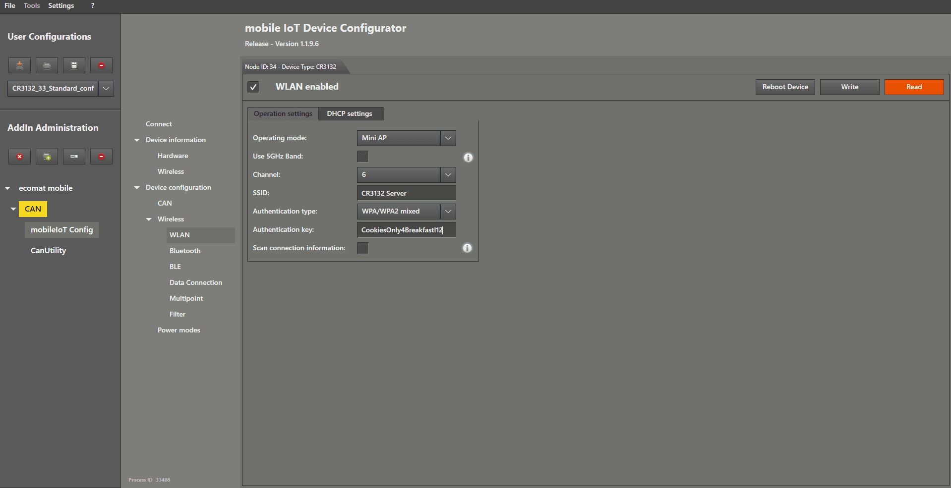
Now check the box in the top-left corner of the settings window to enable WLAN.
Set Operating Mode to “ Mini AP ” by opening the dropdown menu and selecting it.
Disable the " 5 GHz band " by unchecking the box.
Choose a " WLAN channel" from the dropdown menu.
Enter the name for your WLAN in the SSID text field on the right-hand side of “ SSID ”.
For safety reasons, choose your authentication type in the dropdown field.
With FW 3.1 and above , this must be " WPA/WPA2 mixed" !
If you choose any other setting ( FW 3.1 and above) , the devices will not connect to each other.
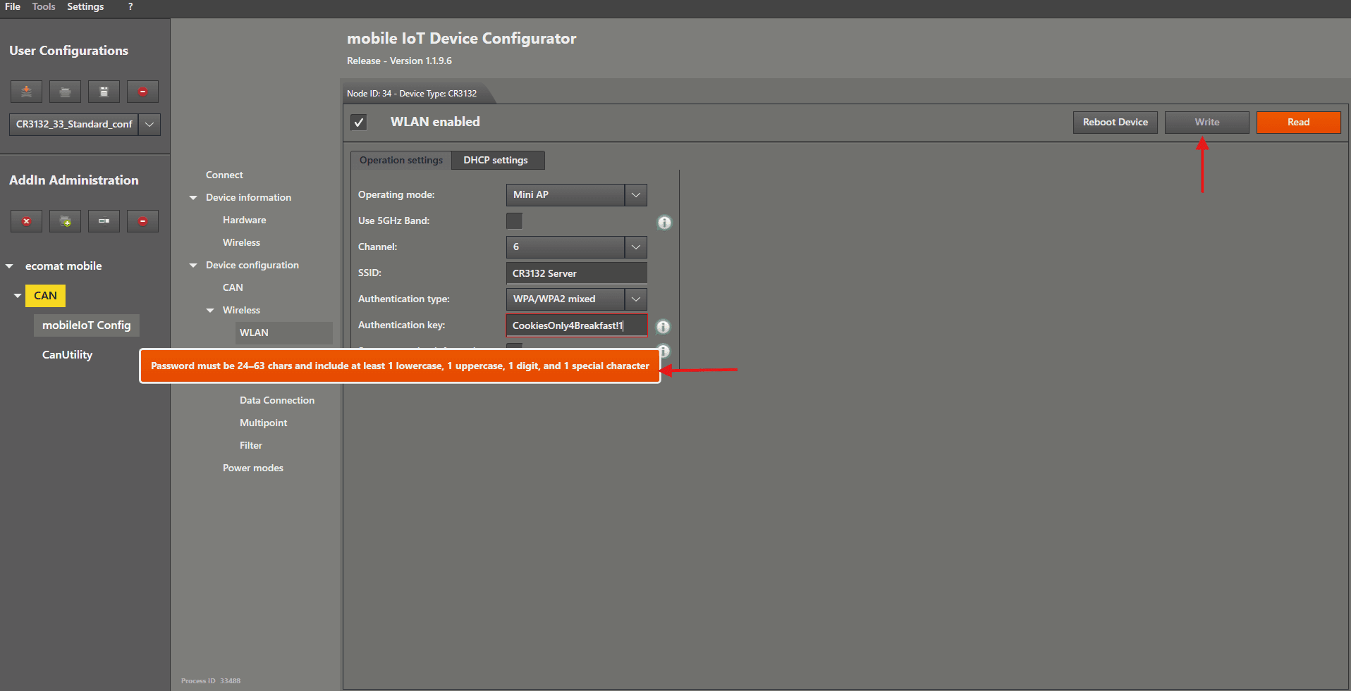
Type your authentication key into the text field.
The minimum requirements will be shown after you enter the first character, and you will not be able to write the settings until your authentication key meets the requirements.
Then left mouse click the “ Write ” button.
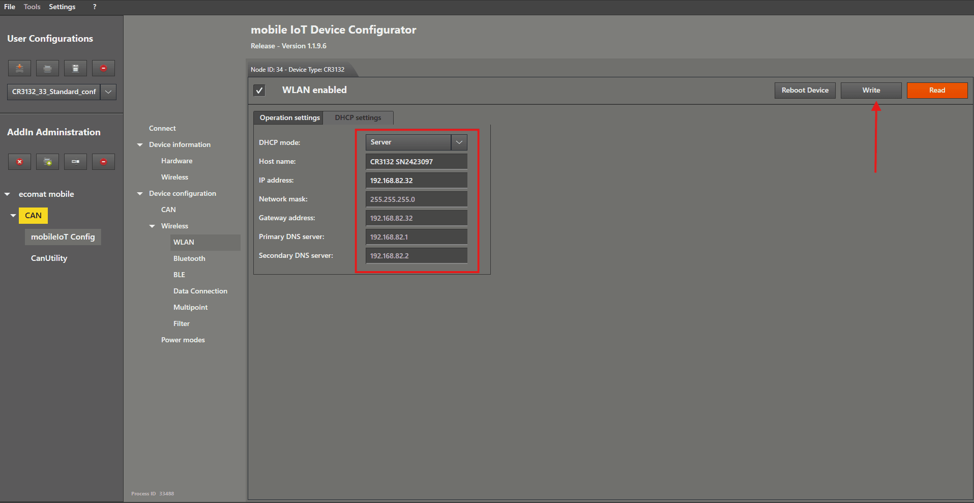
We move on by left mouse clicking on “ DHCP settings ”.
Here, there are two important steps:
Set the “ DHCP mode ” in the dropdown menu to “ Server ” (this should be the default setting).
Then type in the IP address for this device.
I recommend choosing the same number in the last IP segment as the Node ID to make it easier to remember (if possible).
The IP address of the server device will be needed later for the client device to connect.
Then left mouse click the “ Write ” button.
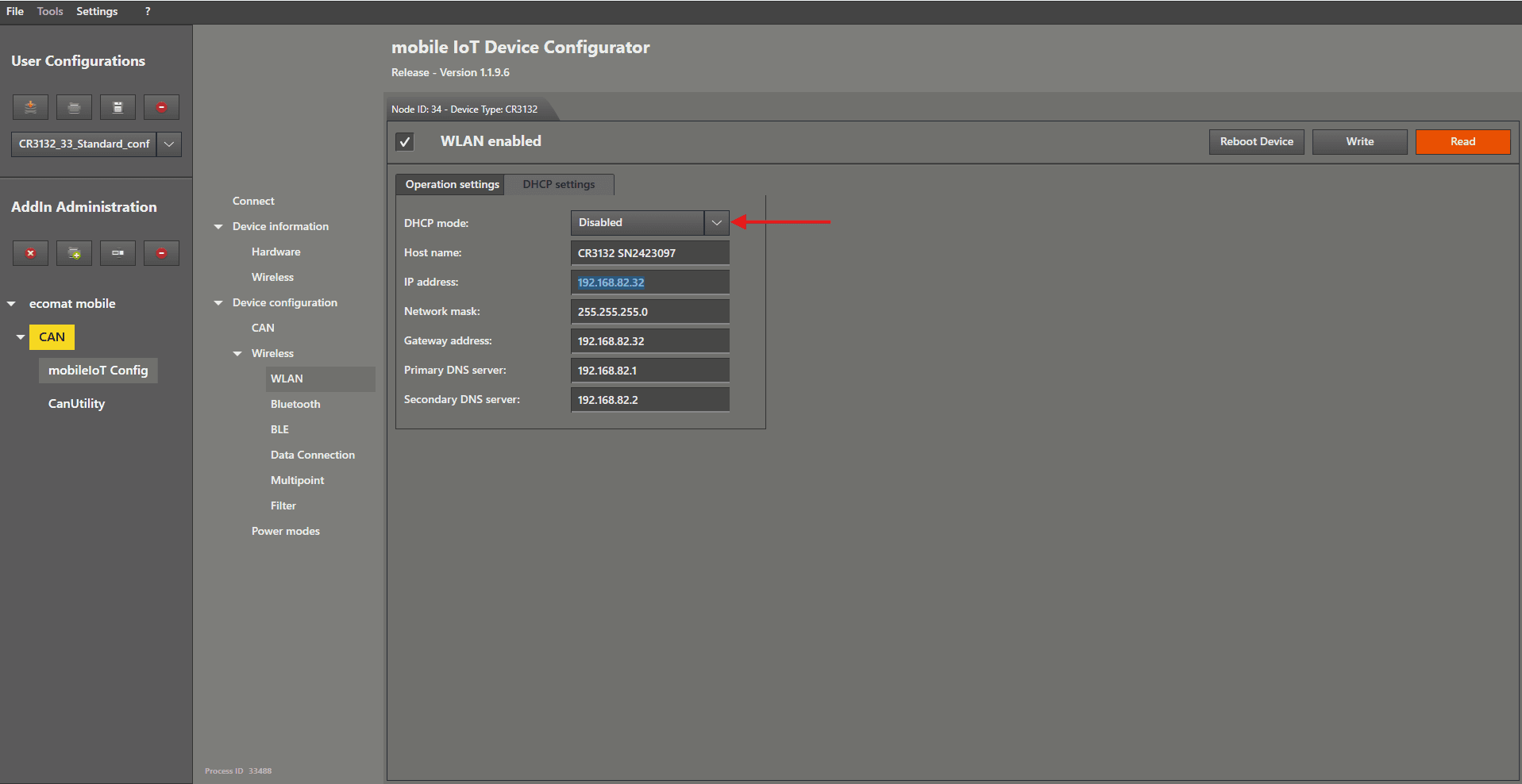
It is also possible to Disable the DHCP and configure all by hand on both devices.
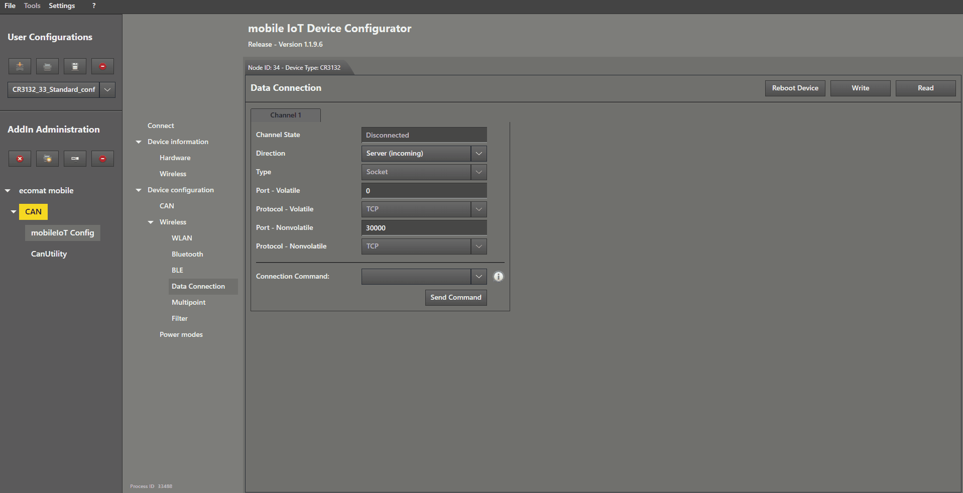
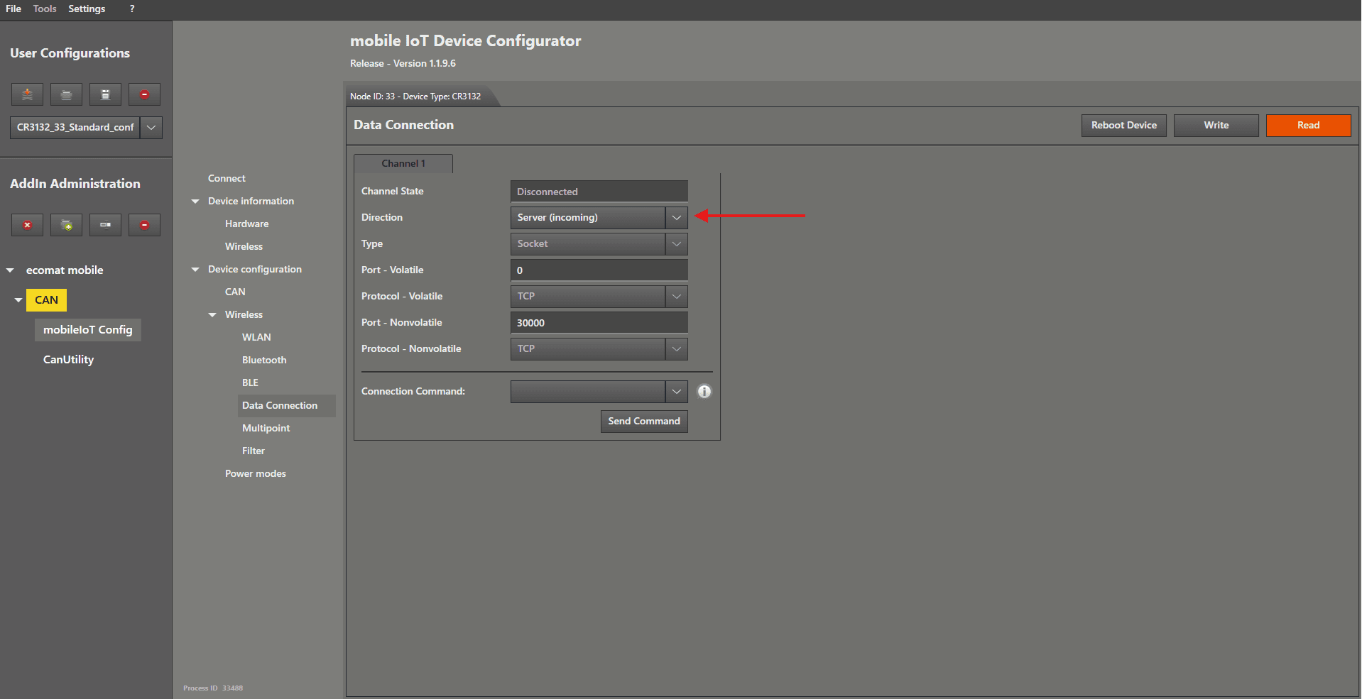
For the next part, left mouse click on “ Data Connection ” in the menu.
It should be configured by default, as shown in the picture below.
If everything matches, simply left mouse click on “ Write ” to confirm.
That was all that needs to be done to configure the server device .
The last step is to restart the device .
Now disconnect your server device from the cable and connect the device you want to configure as a client.
Connect the device.
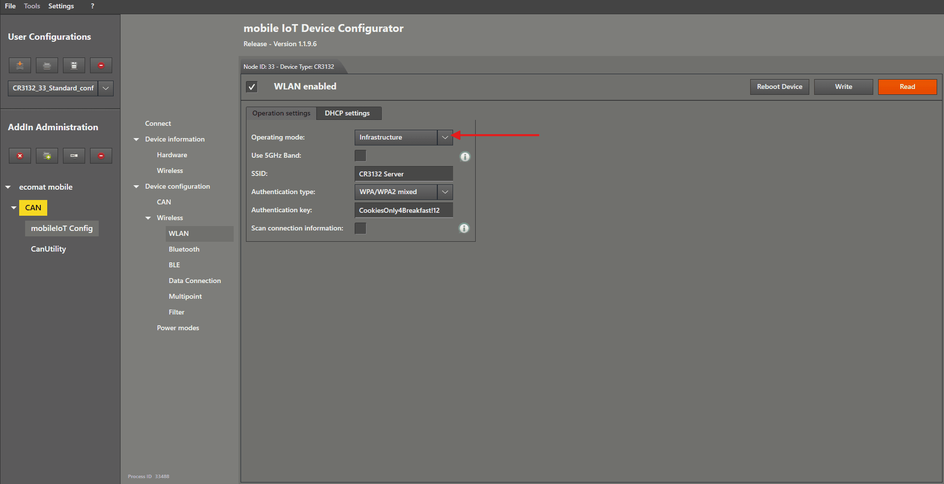
After the connection process, left mouse click on “ WLAN ” again.
Change “ Operating mode ” to “ Infrastructure ” by selecting it from the dropdown menu.
The SSID should already be stored by the MNTT add‑in — just verify the information again.
Then left mouse click the “ Write ” button.
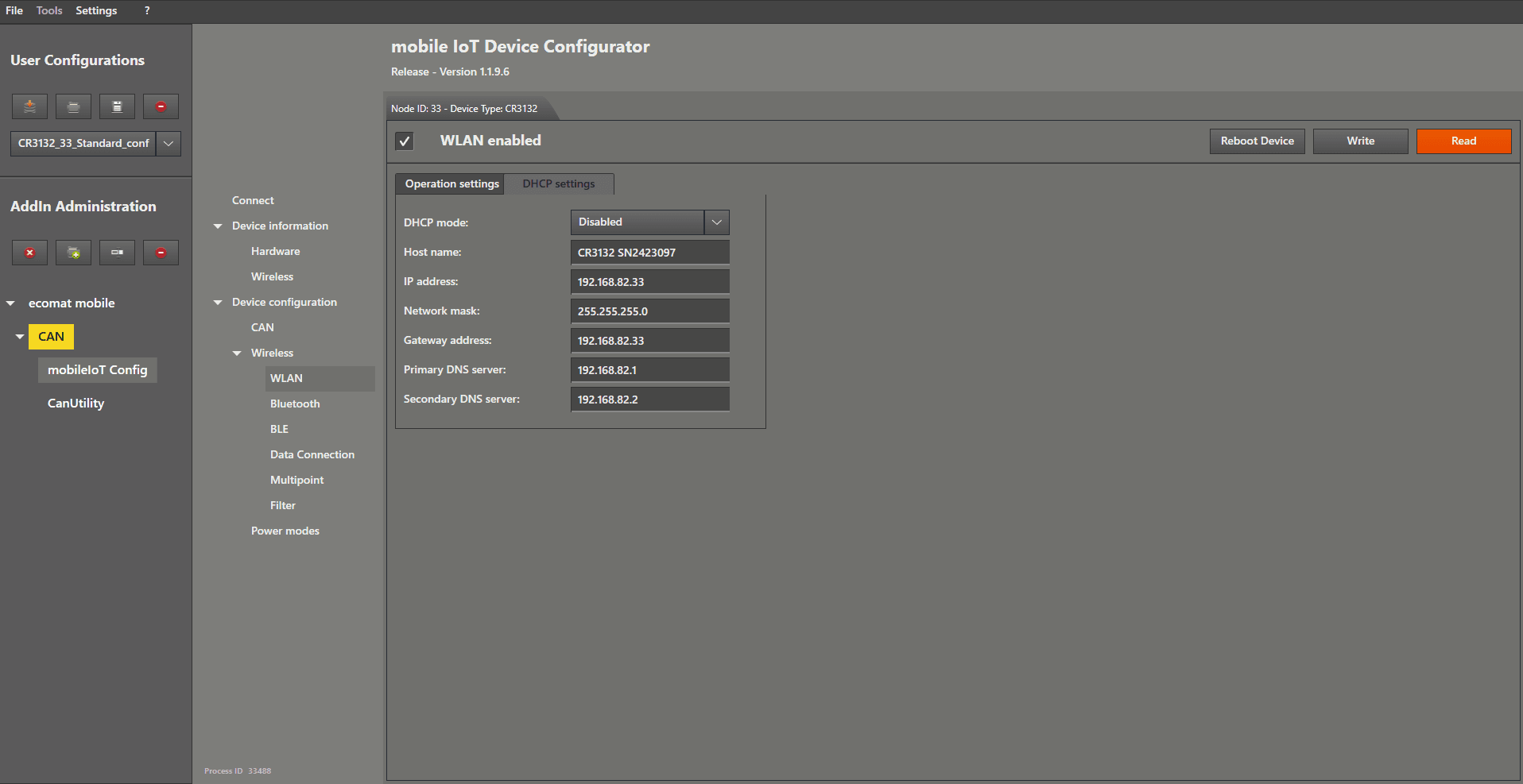
We move on by left mouse clicking on “ DHCP settings ”.
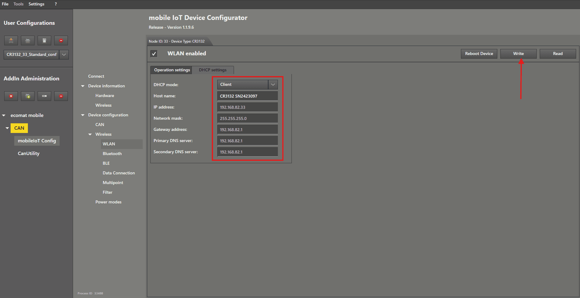
Set the “ DHCP mode ” in the dropdown menu to “ Client ”
Then the IP address for this device and all other related settings will be locked, because the DHCP server will configure them automatically later.
Then left mouse click the “ Write ” button.
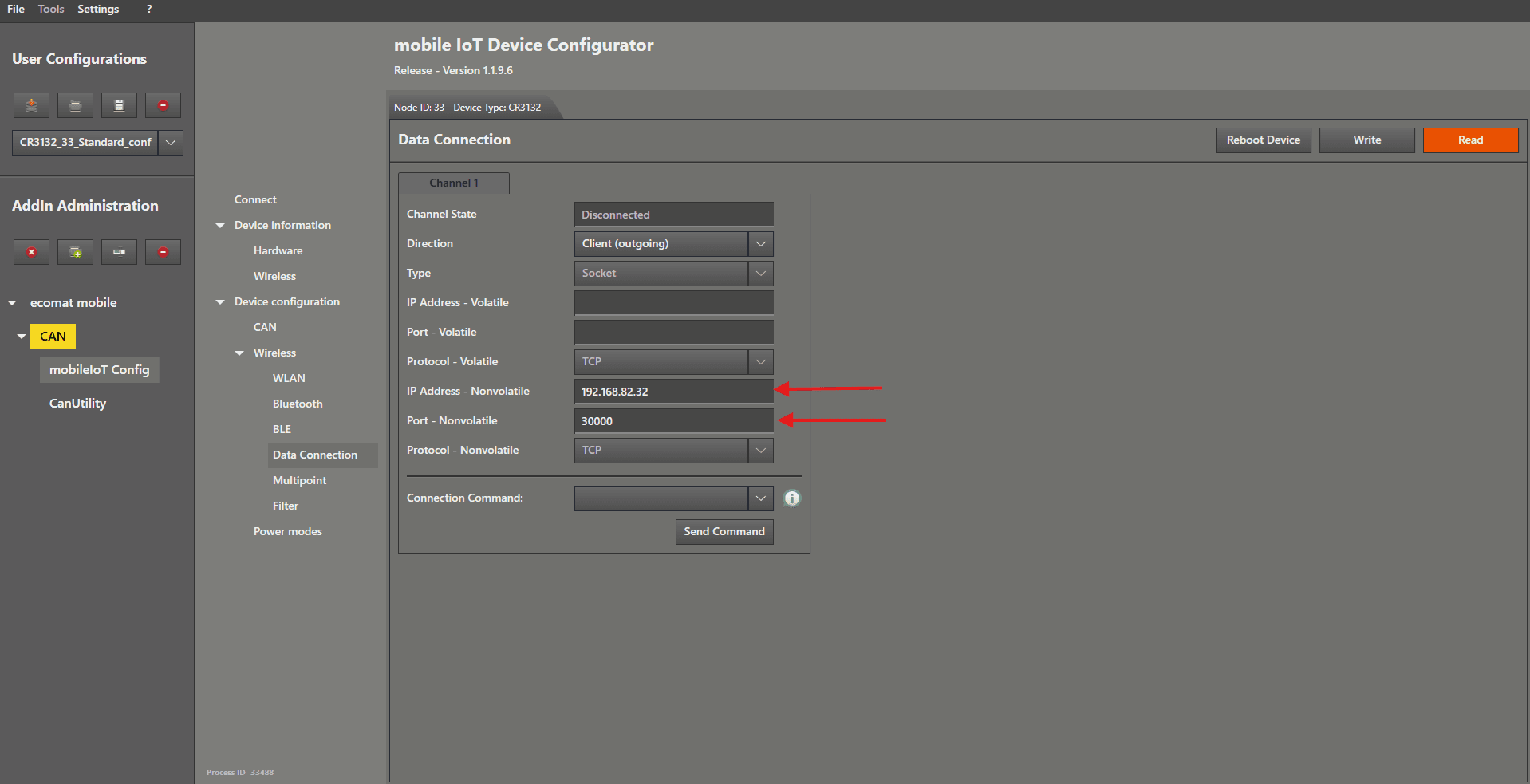
For the next part, left mouse click on “ Data Connection ” in the menu.
Change “ Direction ” to “ Client(outgoing) ” by selecting it from the dropdown menu.
Enter the IP from the server device in the " IP-Address - Nonvolatile " text field on the right-hand side of “ IP-Address - Nonvolatile ”.
The " Nonvolatile - Port " should be 30000 by default if not change it to it or to the port you entered for the server.
Then left mouse click the “ Write ” button.
Reboot the client device , then reconnect the server device .
Ideally, do not connect both devices to the same CAN‑Bus .
If the bridge establishes a connection while both are on the same CAN‑Bus, a communication loop may occur.
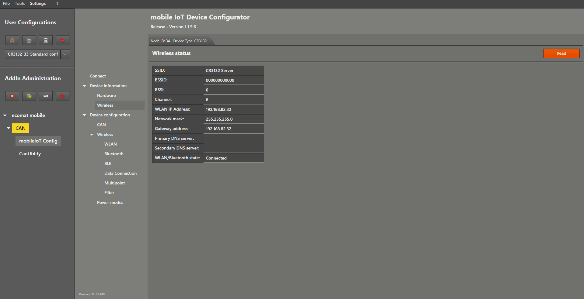
You can check the connection status by left mouse clicking on the “ Wireless ” menu item located below “ Hardware ” in the menu.